The website uses cookies to make the website work properly and improve your experience. More information can be found in Cookie policy.
ERROR: Sequence blowing filter programator in alarm (-KXX.X)

ERROR: Sequence blowing filter programator in alarm (-KXX.X)
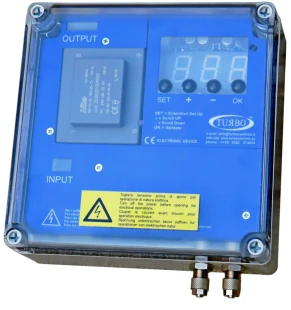
The device that controls the blowing out of the cartridges in the filter is faulty or has no power supply. It is necessary to check on the device itself, which is mounted on the filter. The device error code may be displayed on the device screen, if nothing appears on the screen, it is necessary to check the power supply (230V AC, via relay).
Read the error code from the device screen and check it in the manufacturer's table.
The blowout programmer comes in two versions:
- ECONOMISER SERIES E2T
- SEQUENCER SERIES E1T
ECONOMISER SERIES E2T:
| No. | Description | Action |
|
E01 |
F05 set to 24 Vdc Vac jumper detected |
For 24 Vdc, switch the device off and move the AC/DC jumpers to DC. For 24 Vac, press OK, then press SET, set the function F05 using "+" and "-", select A24 and press OK to confirm. |
| E02 |
F05 set to 24 Vac Vdc jumper detected |
For 24 Vac, switch the device off and move the AC/DC jumpers to AC. For 24 Vdc, press OK, then press SET, set the function F05 using "+" and "-", select d24 and press OK to confirm. |
| E03 |
F05 set to 24 Vac or Vdc Voltage out of range detected |
To use 24V valves, switch the device off and move the output voltage selection jumper to 24V. If the jumper is in the correct position, press OK, then SET, select the F05function with "+" and "-", set 115 or 230 (as jumper) and press OK. |
| E04 |
F05 set to 115 Vac Voltage out of range detected |
To use 115V valves, switch the device off and move the output voltage selection jumper to 115V. If the jumper is in the correct position, press OK, then SET, select the F05 function with "+" and "-", set 115 or 230 (as jumper) and press OK. |
| E05 |
F05 set to 230 Vac Voltage out of range detected |
To use 230V valves, switch the device off and move the output voltage selection jumper to 230V. If the jumper is in the correct position, press OK, then SET, select the F05 function with "+" and "-", set a24, d24 or 115 (as jumper) and press OK. |
| E06 | Solenoid valve current lower than minimum threshold or disocnnected solenoid valve | Check correct connection of the solenoid valve and respective data. The alarm is self-reset. |
| E07 | Solenoid valve current higher than maximum threshold | Check correct connection of the solenoid valve and respective data. The alarm is self-reset. |
| E08 |
Output short circuit. Alarm The signaling of the code E08 alternates with tthe indication of the interested output is shown as Uxx where xx is the number of the output and the value of dP. |
Switch the device off and back on after having checked the solenoid valve system. |
| E09 |
dP maximum pressure exceeded (F10) Detected for longer than 20 seconds. |
Check state of filtering elements. |
| E10 | dP sensor hardware offset out of range. | The self-calibration of the dP sensor has determined that a value is out of range. Disconnect the air tubes and repeat the function. Take the device to be serviced if the alarm occurs again. |
| E11 | Maintenance deadline reached | Carry out maintenance. |
| E12 |
dP sensor full-scale value reached Immediate reporting without any delay. |
Check state of filtering elements.. IMPORTANT: Running in this condition may damage the device. |
| E13 | Minimum dP alarm value ranging from F12 to F21 (warning: the alarm is generated with a fixed delay of 60 seconds). | Check the status of the filtering elements. |
| E14 |
Indicates that a valve in short circuit has been excluded from the cycle. The signaling of the code E14 alternates with the indication of the interested output is shown as Uxx where xx is the number of the output and the value of dP. An output is considered a short circuit if not responding for 3 following activations. An activation without error resets the counting. |
Switch the device off and back on after having checked the solenoid valve system. |
SEQUENCER SERIES E1T:
| Št. | Opis | Ukrep |
|
E01 |
F05 set to 24 Vdc - Vac jumper detected |
For 24 Vdc, switch the devide off and move the AC/DC jumpers to DC. For 24 Vac, press OK, then press SET, set the function F05 using "+" and "-", select A24 and press OK to confirm. |
| E02 | F05 set to 24 Vac - Vdc jumper detected |
For 24 Vac, switch the device off and move the AC/DC jumpers to AC. For 24 Vdc, press OK, then press SET, set the function F05 using "+" and "-", select d24 and press OK to confirm. |
| E03 |
F05 set to 24Vac or Vdc Voltage out of range detected |
To use 24V valves, switch the device off and move the output voltage selection jumper to 24V. If the jumper is in the correct position, press OK, then SET, select the F05 function "+" and "-", set 115 or 230 (as jumper) and press OK. |
| E04 |
F05 set to 115 V Voltage out of range detected |
To use 115V valves, switch the device off and move the output voltage selection jumper to 115V. If the jumper is in the correct position, press OK, then SET, select the F05 function with "+" and "-", set 115 or 230 (as jumper) and press OK. |
| E05 |
F05 SET TO 230 V Voltage out of range detected |
To use 230V valves, switch the device off and move the output voltage selection jumper to 230V. If the jumper is in the correct position, press OK, then SET, select the F05 function with "+" and "-", set a24, d24 or 115 (as jumper) and press OK. |
| E06 | Solenoid valve current lower than minimum threshold or disconnected solenoid valve | Check correct connection of the solenoid valve and respective data. The alarm is self-reset. |
| E07 | Solenoid valve current higher than maximum threshold | Check correct connection of the solenoid valve and respective data. The alarm is self-reset. |
| E08 |
Output short circuit. Alarm The signaling of the code E08 alternates with the indication of the interested output is shown as Uxx where xx is the number of the output. |
Switch the device off and back on after having checked the solenoid valve system. |
| E11 | Maintenance deadline reached | Carry out maintenance. |
| E14 |
Indicates that a valve in short circuit has been excluded from the cycle. The signaling of the code E14 alternates with the indication of the interested output is shown as Uxx where xx is the number of the output. An output is cnosidered a short circuit if not responding for 3 following activations. An activation without error resets the counting. |
Switch the device off and back on after having checked the solenoid valve system. |
If you need additional information, call the Gostol TST service department.
Žarko Rejec
M: 00386 40 725 594
E: zarko.rejec@gostol-tst.eu