The website uses cookies to make the website work properly and improve your experience. More information can be found in Cookie policy.
ERROR: The name of the drive that the inverter is driving - In error (-XX.X)

ERROR: The name of the drive that the inverter is driving - In error (-XX.X)
This error can occur on any inverters, for example; fan, elevator, rollers, turbines. We open the electrical cabinet and find the inverter in error, the label from the error text must match the label on the label. A faulty inverter usually also has one red light on, which indicates an error.
Danffoss:
- We place keyboard to this invertor, usually only one inverter has a keyboard, which can be moved.
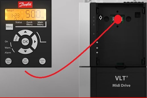
- Read the active alarm code from the screen and check it in the manufacturer's instructions..
| No. | Description | Warning | Alarm | Trip lock | Cause |
| 2 | Live zero error | x | x | - | The signal on terminal 53 or 54 is less than 50% of value set in parameter 6-1 Terminal 53 Low Voltage, parameter 6-20 Terminal 54 Low voltage, and parameter 6-22 Terminal 54 Low Current. |
| 3 | No motor | x | - | - | No motor has been connected to the output of the frequency converter. |
| 4 | Mains phase loss1) | x | x | x | Missing phase on the supply side, or the voltage imbalance is too high. Check the supply voltage. |
| 7 | DC overvoltage1) | x | x | - | DC-link voltage exceeds limit. |
| 8 | DC undervoltage1) | x | x | - | DC-ling voltage drops below the voltage warning low limit. |
| 9 | Inverter overloaded | x | x | - | More than 100% load for too long. |
| 10 | Motor ETR overtemperature | x | x | - | Motor is too hot due to more than 100% load for too long. |
| 11 | Motor thermistor overtemperature | x | x | - | Thermistor or thermistor connection is disconnected, or the motor is too hot. |
| 12 | Torque limit | x | x | - | Torque exceeds value set in either parameter 4-16 Torque Limit Motor Made or parameter 4-17 Torque Limit Generator Mode. |
| 13 | Overcurrent | x | x | x | Inverter peak current limit is exceeded. If this alarm occurs on power-up, check whether power cables are mistakenly connected to the motor terminals. |
| 14 | Ground fault | - | x | x | Discharge from output phase to ground. |
| 16 |
Short circuit |
- | x | x | Short circuit in motor or on motor terminals. |
| 17 | Control word timeout | x | x | - | No communication to frequency converter. |
| 25 | Brake resistor short-circuited | - | x | x | Brake resistor is short-circuited, thus the brake function is disconnected. |
| 26 | Brake overload | x | x | - | The power transmitted to the brake resistor over the last 120 s exceds the limit. Possible corrections: Decrease brake energy via lower speed or longer ramp time. |
| 27 | Brake IGBT / Brake chopper short-circuited | - | x | x | Brake transistor is short-circuited, thus the brake function is disconnected. |
| 28 | Brake check | - | x | - | Brake resistor is not connected / working. |
| 30 | U phase loss | - | x | x | Motor phase U is missing. Check the phase. |
| 31 | V phase loss | - | x | x | Motor phase V is missing. Check the phase. |
| 32 | W phase loss | - | x | x | Motor phase W is missing. Check the phase. |
| 34 | Fieldbus fault | x | x | - | PROFIBUS communication issues have occurred. |
| 35 | Option fault | - | x | - | Fieldbus detects internal faults. |
| 36 | Mains failure | x | x | - | This warning / alarm is only active if the supply voltage to the frequency converter is less thant the value set in parameter 14-11 Mains Voltage at Mains Fault, and parameter 14-10 Mains Failure is NOT se to [0] No Function. |
| 38 | Internal fault | - | x | x | Contact the local Danfoss supplier. |
| 40 | Overload T27 | x | - | - | Check the load connected to terminal 27 or remove short-circuit connection. |
| 46 | Gate drive voltage fault | - | x | x | - |
| 47 | 24 V supply low | x | x | x | 24 V DC may be overloaded. |
| 51 |
AMA check Unom and Inom |
- | x | - | Wrong setting for motor voltage and / or motor current. |
| 52 | AMA low Inom | - | x | - | Motor current is too low. Check the settings. |
| 53 | AMA big motor | - | x | - | The power size of the motor is too large for the AMA to operate. |
| 54 | AMA small motor | - | x | - | The power size of the motor is too small for the AMA to operate. |
| 55 | AMA parameter range | - | x | - | The parameter values of the motor are outside of the acceptable range. AMA does not run. |
| 56 | AMA interrupt | - | x | - | The AMA is interrupted. |
| 57 | AMA timeout | - | x | - | - |
| 58 | AMA internal | - | x | - | Contact Danfoss. |
| 59 | Current limit | x | x | - | Frequency converter overload. |
| 61 | Encoder loss | x | x | - | - |
| 63 | Mechanical brake low | - | x | - | Actual motor current has not exceeded release brake curent within start delay time window. |
| 65 | Control card temp | x | x | x | The cutout temperature of the control card has exceeded the upper limit. |
| 67 | Option change | - | x | - | A new option is detected or a mounted option is removed. |
| 68 | Safe Torque off | x | x | - | STO is activated. If STO is in manual restart mode (default), to resume normal operation, apply 24 V DC to terminals 37 and 38, and initiate a reset signal (via fieldbus, digital I/0, or [Reset] / [Off Reset] key). If STO is in automatic restart mode, applying 24 V DC to terminals 37 and 38 automatically resumes the frequency converter to normal operation. |
| 69 | Power card temp | x | x | x | The cutout temperature of the power card has exceeded the upper limit. |
| 80 | Drive initialized to default value | - | x | - | All parameter settings are initialized to default settings. |
| 87 | Auto DC braking | x | - | - | Occurs in IT mains when the frequency converter coasts, and the DC voltage is higher than 830 V for 400 V units and 425 V for 200 V units. The motor consumes energy on the DC link. This function can be enabled / disabled in parameter 0-07 Auto DC Braking. |
| 88 | Option detection | - | x | x | The option is removed successfully. |
| 95 | Broken belt | x | x | - | - |
| 120 | Position control fault | - | x | - | - |
| 188 | STO internal fault | - | x | - | 24 V DC supply is connected to only 1 of the 2 STO terminals (37 and 38), or failure in STO channels is detected. Ensure that both terminals are connected to 24 V DC supply, and that the discrepancy between the signals at the 2 terminals is less than 12 ms. If the fault still occurs, contact the local Danfoss supplier. |
| nw run | Not while running | - | - | - | Parameter can only be changed when the motor is stopped. |
| Nap | A wrong password was entered | - | - | - | Occurs when using a wrong password for changing a password-protected parameter. |
1) These errors can cause fluctuations in the mains supply. Installing a Danfoss line filter can eliminate this problem.
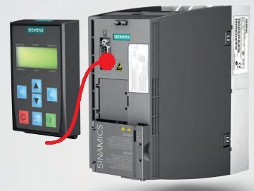
Siemens
If you need additional information, call the Gostol TST service department.
Žarko Rejec
M: 00386 40 725 594
E: zarko.rejec@gostol-tst.eu